 Elektrikli Araç Şarj İstasyonları Aslında Nasıl Çalışır?
Nov 13, 2025
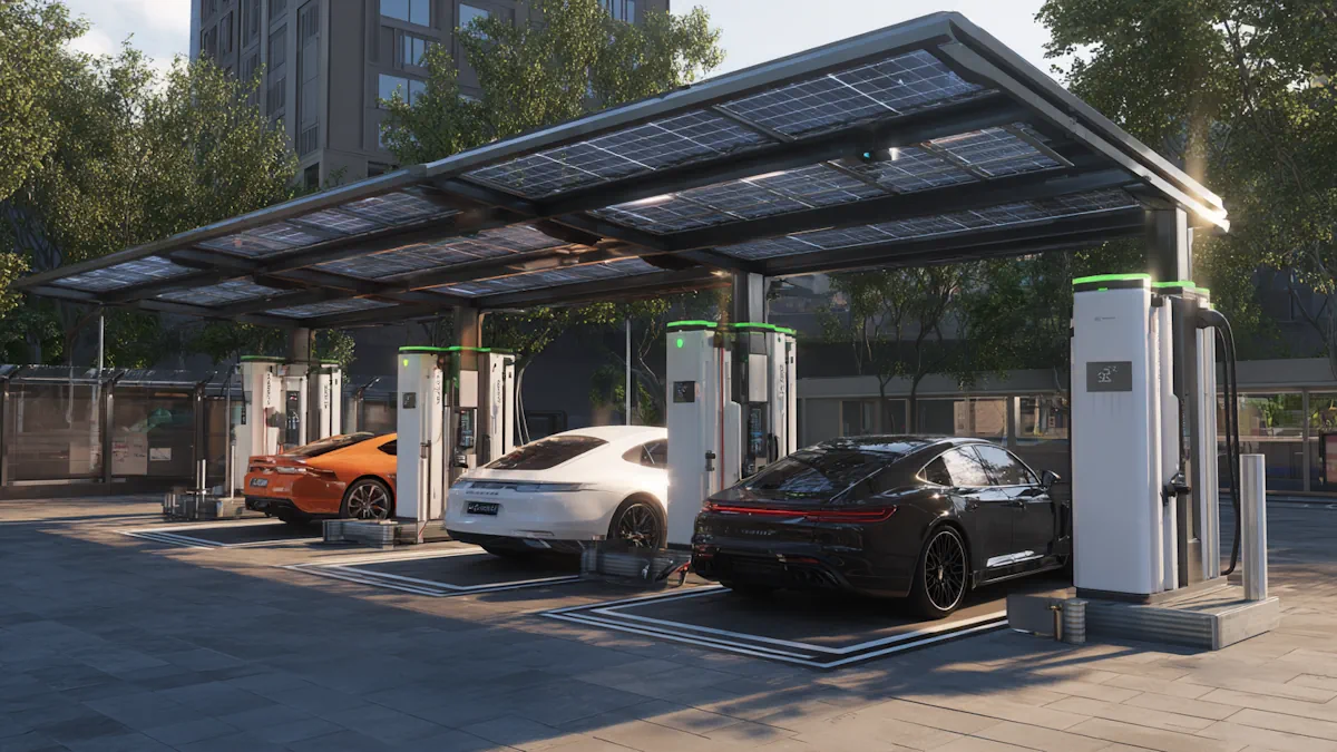
Elektrikli araç şarj istasyonları üç akışı koordine eder: güç, düşük voltajlı kablo sinyali ve bulut verileri. Böylece araç ve istasyon sınırlar konusunda anlaşır, kontaktörleri güvenli bir şekilde kapatır, ölçülen enerjiyi iletir ve oturumu sonlandırır. İlk kez kullanıcı için hızlı yolBir istasyon bulun → kimlik doğrulaması yapın (RFID, uygulama veya Tak ve Şarj) → takın ve oturumun başlamasını izleyin. Bir istasyon aslında ne yapar?Bir istasyon, bir prizden çok daha fazlasıdır. Güvenli güç yönlendirir, limitleri kabul etmek için araçla düşük voltajlı sinyaller alışverişinde bulunur, oturumu yetkilendirmek ve kaydetmek için bir arka uçla iletişim kurar ve faturalandırılabilir bir kayıt oluşturur. Süreç, uçtan uca kontrol edilir, ölçülür ve denetlenebilir. Üç akış tek bir görünümdeGüç: şebeke veya yerinde üretim → dağıtım paneli → kabin veya duvar kutusu → kontaktör → araç aküsüKontrol: Kontrol-pilot sinyalizasyonu (IEC 61851-1 / SAE J1772) sınırları duyurur → araç bu sınırlar dahilinde talepte bulunur → güvenli duruma ulaşılırVeri: Yetkilendirme, tarifeler, oturum durumu, sayaç değerleri ve makbuz için bir şarj protokolü (örneğin, OCPP) aracılığıyla istasyon ↔ bulut AC ve DCAC şarjda, AC'den DC'ye dönüşüm, aracın yerleşik şarj cihazının (OBC) içinde, mütevazı bir güçte gerçekleşir.DC hızlı şarj ile dönüşüm kabine taşınır; doğrultucu modülleri yüksek akımlı DC'yi doğrudan aküye sağlarken araç talebi denetler ve sınırlar. AC ve DC rolleri ve sinyalleriÖğeAC şarjı (ev ve iş yeri)DC hızlı şarj (genel DC)AC→DC'nin gerçekleştiği yerArabanın içinde (araç içi şarj cihazı)Kabinin içinde (doğrultucu modülleri)Tipik güç3,7–22 kW50–400 kW+Akım nasıl ayarlanır?İstasyon sınırları dahilinde araç talepleriİstasyon modülleri, saha ve termal sınırlar dahilinde araç talebini karşılarDarboğaz kuralıOturum oranı = min(araç kapasitesi, istasyon kapasitesi, site sınırları)Oturum oranı = min(araç kapasitesi, istasyon kapasitesi, site sınırları)Kablo ve arayüz (bölgeye göre)Tip 2 veya J1772CCS2, CCS1, GB/T veya NACSKablo üzeri sinyalizasyonKontrol Pilotu 1 kHz PWM akım tavanını bildirir; Yakınlık Pilotu kabloyu ve mandalı tanımlarAynı düşük voltajlı zincir artı yüksek voltajlı kilitlemeler ve yalıtım kontrolleriEmniyet zinciriAna kontaktör kapanmadan önce durum geçişleri; kaçak koruması mevcutAynı zincir artı paket düzeyinde korumalarBulut bağlantısıOturum, tarife, durum, hatalar, donanım yazılımıAynı, daha fazla telemetri ve termal veriyle Telde neler oluyor?Herhangi bir yüksek voltaj oluşmadan önce, istasyon ve araç, konnektördeki iki düşük voltaj hattı üzerinden iletişim kurar. Kontrol pilotu 1 kHz'lik bir kare dalgadır; görev döngüsü, istasyonun mevcut tavan değerini bildirir. Araç bu tavan değerini okur ve asla daha fazlasını talep etmez. Yakınlık pilotu, istasyona hangi kablonun bağlı olduğunu ve mandalın takılı olup olmadığını bildirir. Sistem ancak bu kontroller tamamlandıktan sonra bekleme durumundan enerjili duruma geçer. Fiziksel arayüz ve kullanım notlarına ihtiyaç duyan okuyucularımız için, Tip 2 EV konnektörüKabuk geometrisi, mandal davranışı ve kablo derecelendirme temelleri için sayfa. Sıcak takmayı önleyen güvenlik zinciriMekanik: Mandal, fişi yerinde tutar; istasyon bunu algılar.Elektrik: Topraklama ve izolasyon kontrolleri geçti; kaçak koruma devrede.Mantıksal: Araç hazır sinyali verdiğinde istasyon enerjili duruma geçer.Güç: Ana kontaktör (yüksek güç rölesi) kapanır; izleme oturum boyunca devam eder. Herhangi bir koşul başarısız olursa, kontaktör açılır ve güç durur. İstasyon bulutla nasıl iletişim kuruyor?İstasyonlar nadiren tek başına çalışır. OCPP (Açık Şarj Noktası Protokolü) aracılığıyla ünite durumu bildirir, tarifeleri ve güncellemeleri alır, oturumları açıp kapatır ve sayaç değerlerini ve hata kodlarını yükler. Tipik mesaj akışı Yetkilendir → İşlemi Başlat → Sayaç Değerleri (periyodik) → İşlemi Durdur'u, ayrıca Kalp Atışı ve Aygıt Yazılımı yönetimini içerir. Sertifikalı bir sayaç, enerjiyi kilovatsaat cinsinden kaydeder; politika gereği zamana veya oturuma bağlı ücretler eklenebilir, ancak enerji ölçümü faturayı belirler. Eklentiden faturalandırmaya: yedi adımlı bir zaman çizelgesi1.Fiziksel bağlantı: Mandal tık sesi gelene kadar konektörü takın; istasyon kablo tipini ve kapasitesini algılar.2.Güvenlik kontrolleri: Topraklama ve izolasyon doğru görünüyor; istasyon 1 kHz kontrol sinyalini yayınlıyor.3.Yetenek duyurusu: Görev döngüsü, bu çıkış ve kablo için izin verilen maksimum akımı belirtir.4.Araç hazır: Araç uygun bir akımı onaylar ve talep eder veya DC el sıkışmasını başlatır.5.Enerjilendirme: İstasyon kontaktörlerini kapatır; koruyucu cihazlar devreye girer ve tetikte kalır.6.Ölçülü teslimat: Enerji ölçülür ve kaydedilir; limitler sıcaklık, yük yönetimi veya saha politikasına göre ayarlanır.7.Sonlandır ve yerleştir: Buton, uygulama, RFID veya hedefe ulaşıldığında durdurma; faturalandırma için kayıtlar sonlandırılır. Oturumlar neden olması gerekenden daha sık başarısız oluyor?• Fiziksel uyum ve mandal: kir, hizalama hatası, aşınmış contalar veya eğilmiş bir yay yakınlık sinyalini engelleyebilir.• Kablo ve gerilim azaltma: keskin kıvrımlar, hasarlı kılıf veya su girişine karşı tetik koruması.• Aralık dışı sinyal verme: zayıf temas veya korozyon düşük voltaj seviyelerini değiştirir, böylece araç hiçbir zaman geçerli bir durum görmez.• Arka uç gecikmeleri: Bulutun yetkilendirmesi çok uzun sürerse, istasyon zaman aşımına uğrar.• Termal sınırlar: Sıcak hava veya tozlu bir filtre akımı düşürür; bazı araçlar Sürüyü korumak için erken durun. Sıcak havalarda yoğun kamusal alanlar için, CCS2 sıvı soğutmalı konnektörUzun seanslar sırasında sap sıcaklığının sabit kalmasına ve kablo ağırlığının yönetilebilir olmasına yardımcı olur. SözlükCkontaktör:ana devreyi bağlayan yüksek güçlü röleDyardımcı çevrim:bir döngü içinde kontrol sinyalinin açık olduğu zaman yüzdesiIyalıtım kontrolü:yüksek voltajlı parçaların toprağa sızmadığının doğrulanmasıTak ve Şarj Et (ISO 15118):aynı kablo üzerinden sertifika tabanlı otomatik kimlik doğrulama SSSSadece fişe takıp çalıştırabilir miyim?Bazı araçlar, sertifika tabanlı otomatik kimlik doğrulama için Tak ve Şarj Et (ISO 15118) standardını destekler. Aksi takdirde, RFID veya operatör uygulamasını kullanın. Oturumum neden başlatılamadı?Mandal tık sesi duyana kadar bastırın, kablo güzergahını kontrol edin (keskin kıvrımlar yok), konektördeki görünür kirleri temizleyin, ardından RFID zaman aşımına uğrarsa uygulamayı deneyin. Şarj işlemi bazen neden yavaşlıyor?İstasyonlar ve araçlar, yüksek şarj durumuna yakın bir zamanda, konektör ısındığında veya saha duraklar arasında güç dengesi sağladığında akımı azaltır. Tam olarak ne faturalandırılıyor?Kilowatt/saat cinsinden enerji baz alınır. Operatörler, zaman veya seans bazlı ücretler ve vergiler ekleyebilir; makbuzda bileşenler listelenir.
DEVAMINI OKU


 IPv6 AĞ DESTEKLENİYOR
 Türk
Türk